

- Define Circuit Element?
- What is the units of electrical elements?
- What is a Capacitor?
- Symbolic representation of Capacitor:
- Internal Structure of capacitor:
- Formula of Capacitance:
- Instantaneous power delivered to the capacitor:
- Stored energy in the capacitor:
- Combination of capacitors:
- Capacitors in series:
- Capacitors in parallel:
- Types of Capacitors:
- What is a Resistor?
- Structure of Resistor:
- Formula of Resistance:
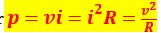
- Instantaneous Power delivered to the Resistor:
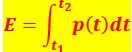
- Stored energy in the Resistor:
- Combination of resistors:
- Resistors in series:
- Resistors in parallel:
- What are the types of Resistors?
- What is a resistor used for?
- What is theory behind resistor?
- How a resistor work in circuit?
- What is the unit of resistance?
- What is an Inductor?
- Formula of Inductance:
- Instantaneous power delivered to the Inductor:
- Stored energy in the Inductor:
- Combination of Inductors:
- Inductor in series:
- Inductors in Parallel:
- Comparison of Resistor, Inductor & Capacitor:
Define Circuit Element?
An electric circuit is made up of many circuit components joined together to provide a closed path that allows electricity to flow. An electrical circuit element is the mathematical representation of an electrical device and is entirely defined by the relationship between voltage and current. As a circuit element is the most fundamental component, it cannot be separated into other devices.
Three fundamental circuit components
- Resistor
- Inductor
- Capacitor
What is the units of electrical elements?
| Elements | Units |
|---|---|
| Voltage | Volt (V) |
| Electric Current | Ampere (A) |
| Resistor | Ohm (Ω) |
| Inductor | Henry (H) |
| Capacitor | Farad (F) |
| Power | Watt (W) |
| Energy | Joule (J) |
Capacitor – Definition, Formula & Types
What is a Capacitor?
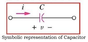
A capacitor is an electrical circuit component that has the capacity to store electrical energy in the form of an electric field. Capacitance is the characteristic of a capacitor that allows it to store electrical energy. Symbolic representation of capacitor is shown below.
Symbolic representation of Capacitor:
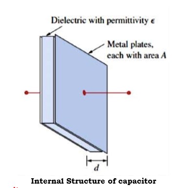
Two metallic plates are separated by an insulating substance to form a basic capacitor. This insulating substance, which is called as dielectric, holds electrical energy in the form of an electric field. There are various varieties of capacitors, such as paper capacitors, air capacitors, mica capacitors, ceramic capacitors, electrolytic capacitors, etc., depending on the dielectric material employed. The structure of capacitor is shown below.
Internal Structure of capacitor:
Formula of Capacitance:
Capacitance is calculated as

where
![]() – The permittivity of the dielectric material between the plates (F/m),
– The permittivity of the dielectric material between the plates (F/m),
A – The surface area of each plate (m2 ), D is the distance between the plates (m)
Capacitance of a capacitor is the ratio of the charge (q) per plate to the applied voltage (v) can also be said C = q/v
Capacitor is a circuit device whose terminal voltage directly proportional to integral of current with respect to time.

Instantaneous power delivered to the capacitor:

Stored energy in the capacitor:

Therefore

Combination of capacitors:
Either the capacitors can be connected in series or parallel.Capacitors in parallel are added together – capacitance increases.In series capacitance is reduced.
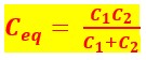
Capacitors in series:
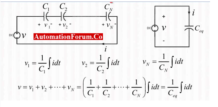
Therefore, equivalent series capacitance is,
Capacitors in parallel:

Therefore, equivalent parallel capacitance is,

Types of Capacitors:
Capacitors are classified based on their polarity as,
- Polarized Capacitors
- Non-Polarized Capacitors
A polarized capacitor is one that has fixed positive and negative polarity markings on its terminals and a fixed terminal polarity. So, only DC circuits can use polarized capacitors. Because the terminal polarity of a non-polarized capacitor is not fixed, it can also be utilized in AC circuits.
Depending on the change in capacitance, the capacitors may be of two types namely fixed capacitors and variable capacitors.
Resistor – Definition, Formulae & Types
What is a Resistor?
A resistor is an electrical circuit component that places electrical friction or resistance in the path of an electric current. Resistance is the property of opposing the flow of current in a circuit. A resistor’s resistance is indicated by the symbol R and expressed in Ohms (Ω).
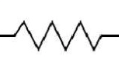
Structure of Resistor:
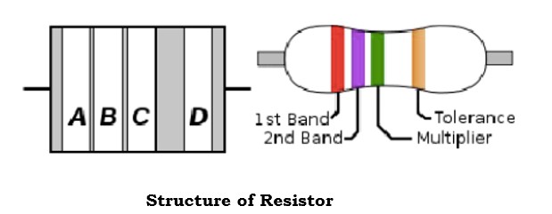
The resistor structure is shown above. In the above structure, we have 4 different bands namely A, B, C & D.
- First band is A which is resistance first significant figure value
- Second band is B which is the second significant figure
- Third band is C which is the decimal multiplier
- Fourth band is D if present that indicates tolerance of value in percent (no color means 20 %)
The value of resistance can be calculated by standard color code per EN60062:2005 is as follows:

From the above table the resistor value can be read from left to right. The below shown is brown, black, yellow, gold then the resistor value is 100KW with 5% tolerance.
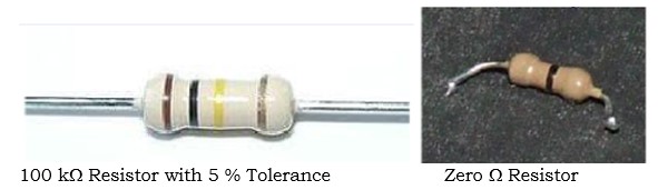
Zero ohm resistors, which has a single black band.These are lengths of wire wrapped in a resistor shaped body that can be substituted for another resistor value in automatic insertion equipment.
Formula of Resistance:
The resistance can be calculated as
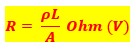
Where, r is resistivity of material (W-m), L is length of conductor (m), A is area of cross-section (m2)
The voltage applied across a resistor directly affects the current flowing through it. An element is referred to as a resistor, in voltage-current relationship if the voltage across it is directly proportional to the current through it.
As Resistance (R)

where V is the applied voltage (v) and I is electric current (A)
Instantaneous Power delivered to the Resistor:
Stored energy in the Resistor:
Combination of resistors:
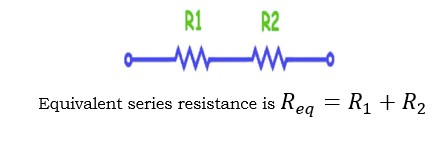
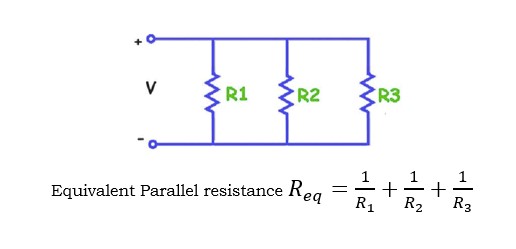
Resistors can be connected in either series or Parallel. Resistors in series arrangement sum up together and resistance increases. In parallel arrangement resistance is reduced.
Resistors in series:
Resistors in parallel:
What are the types of Resistors?
Based on several criteria, resistors can be categorized into various categories. According to Ohm’s law, resistors can be divided into the two categories.
- Linear Resistors
- Non-Linear Resistors
Linear resistors, also known as ohmic resistors, are resistors that adhere to Ohm’s law. The term “non-linear resistor” or “unohmic resistor” is used when a resistor does not follow Ohm’s law.
Depending on the changing of resistance value, there are two types of resistors
- Fixed Resistors
- Variable Resistors
Resistors whose value remains constant and never be changed are known as fixed resistors. Resistors whose value can be varied are known variable resistors.
What is a resistor used for?
The amount of electrical current that can flow through a circuit in an electronic device is controlled or limited by a resistor.
What is theory behind resistor?
Circuit components called resistors obstruct the flow of current. A pure resistor generates heat from electrical energy. This energy is transformed into light, motion, heat, and other types of energy via components like resistors.
How a resistor work in circuit?
Resistors in the circuits stop an excessively high current from harming the breadboard, wires, battery. Also, the resistor regulates the electron flow.
What is the unit of resistance?
The unit of resistance is ohm.
Inductor– Definition, Formula & Types
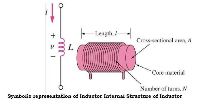
What is an Inductor?
An inductor is essentially a wire with a limited length that has been wound into a coil. An inductor is another fundamental component of a circuit that is used to add inductance to an electrical or electronic circuit. An inductor prevents any change in the electric current. The symbolic representation & internal structure of inductor is shown below.
Formula of Inductance:
Inductance can be calculated by
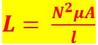
where N is number of turns in coil, A is the cross-sectional area of coil, m2, l is the length of the coil (m) and m is the permeability of the core material H/m.
In terms of the relationship between voltage and current, an element with two terminals whose terminal voltage is directly proportional to the derivative of current with respect to time is known as an inductor.
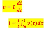
The voltage across the inductor would be zero if the current through it remained constant. An inductor using DC acts like a short-circuit coil. An inductor’s current cannot abruptly change. The ability of an inductor to store a limited amount of energy in the form of a magnetic field is a one specific characteristic. An ideal inductor only stores energy rather than releasing it.
Instantaneous power delivered to the Inductor:

Stored energy in the Inductor:

Combination of Inductors:
Inductors can be connected in either series or Parallel. Inductors in series are added together – inductance increases. In parallel inductance is reduced.
Inductor in series:

Therefore, equivalent series inductance is

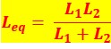
Inductors in Parallel:
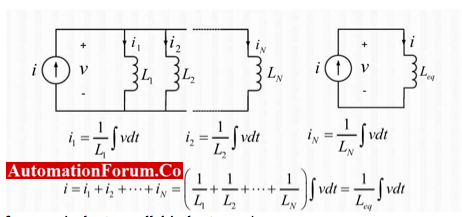
Therefore, equivalent parallel inductance is,
Comparison of Resistor, Inductor & Capacitor:


