
- What is Complementary Split Range Control (CSRC)?
- Example Scenario: Temperature Control in a Chemical Reactor
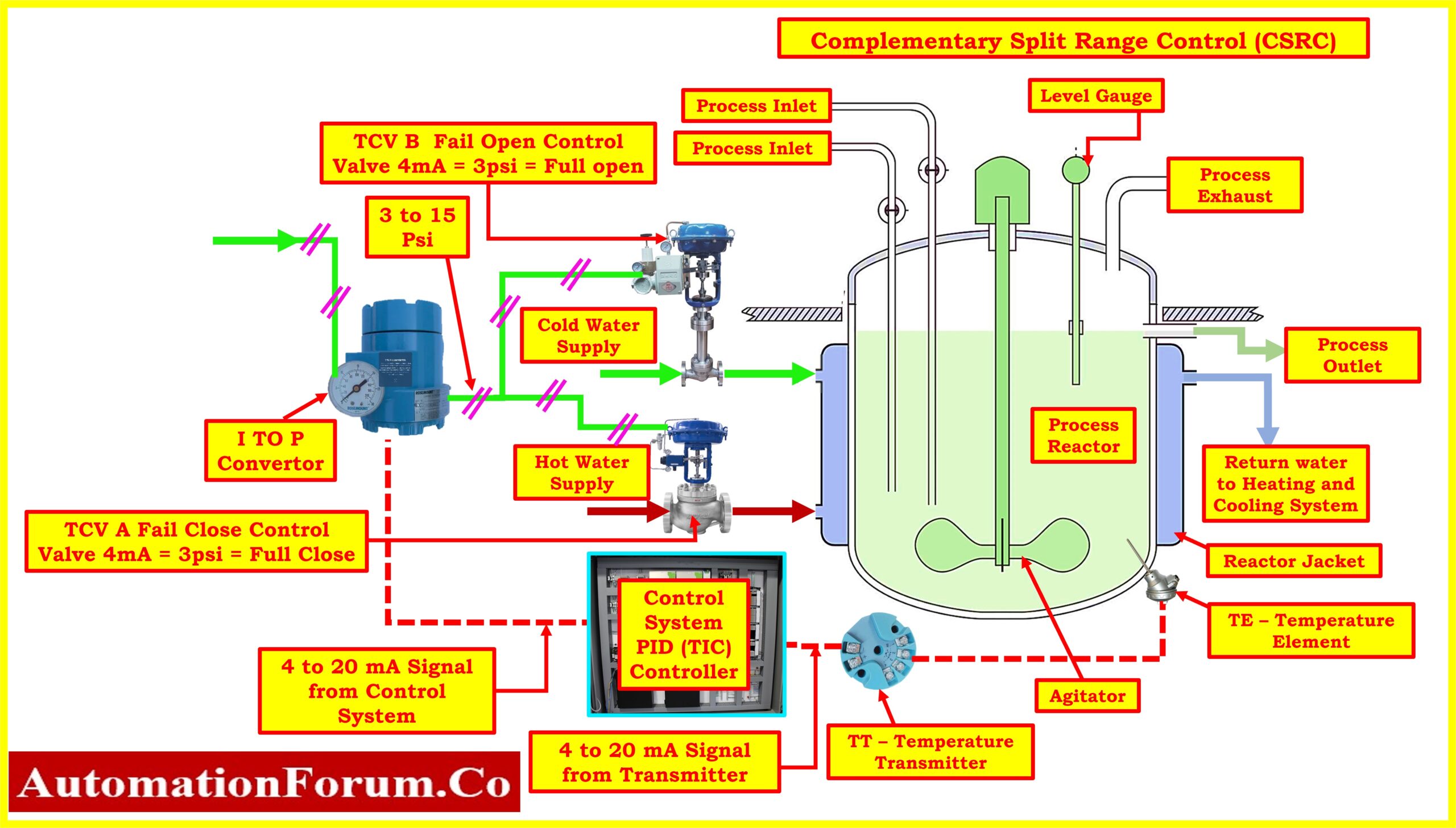
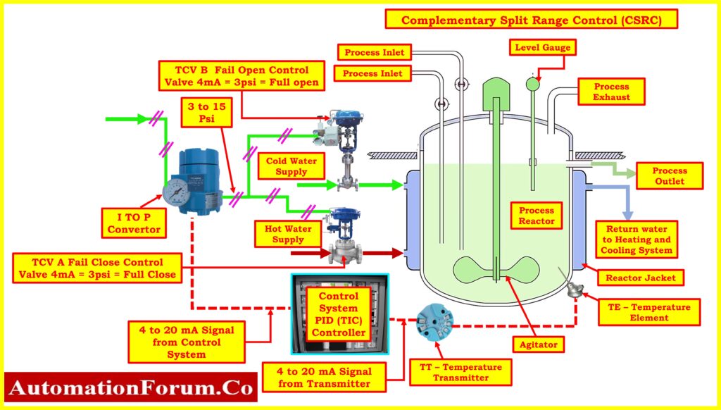
- Components of the Control System
- Control Inputs
- Control Strategy
- CSRC Implementation
- Benefits of Complementary Split Range Control (CSRC)
- Applications of Complementary Split Range Control (CSRC)
- Disadvantages of Complementary Split Range Control (CSRC)
What is Complementary Split Range Control (CSRC)?
- Complementary Split Range Control (CSRC) is a method used in process control systems to regulate a process variable (PV) by manipulating multiple final control elements (e.g., valves or dampers) in a coordinated manner.
- In CSRC, two or more final control elements are used to regulate the same process variable.
- These control elements operate in opposite directions, meaning that when one control element is opening to increase the process variable, the other is closing to decrease it.
- This configuration allows for finer control resolution and better responsiveness compared to using a single control element.
- CSRC is often employed in situations where the process variable needs to be controlled within a narrow range and where rapid and precise adjustments are required.
- By using complementary actions, CSRC can mitigate the effects of deadband and hysteresis inherent in control systems, leading to more stable and accurate control.
- Overall, CSRC is a sophisticated control strategy that enhances the performance and efficiency of process control systems, particularly in applications where precise control is critical.
Example Scenario: Temperature Control in a Chemical Reactor
- Imagine a chemical reactor tasked with producing a specific chemical compound, where maintaining the optimal temperature is critical for the reaction’s success.
- However, due to varying external factors such as ambient temperature changes or feedstock variations, the reactor’s temperature needs to be dynamically controlled to ensure product quality and safety.
- In this scenario, the temperature of a chemical reaction needs to be tightly controlled within a reactor vessel.
- The system employs hot and cooled water streams to regulate the temperature within the vessel.
- The objective is to maintain the temperature within a specified range to ensure optimal reaction conditions and product quality.
Components of the Control System
The control system consists of the following components:
Process System
- The reactor vessel where the chemical reaction takes place.
Temperature Sensing Element
- Within the reactor vessel, a platinum RTD (Resistance Temperature Detector) is installed as the temperature sensing element.
- RTDs are chosen for their high accuracy and stability, making them ideal for precise temperature measurements in industrial applications.
Temperature Transmitter
- Connected to the RTD, a temperature transmitter continuously monitors the temperature within the reactor vessel.
- This transmitter converts the resistance variation of the RTD into a standardized 4 to 20 mA current loop signal, where 4 mA corresponds to the lowest temperature and 20 mA to the highest temperature within the transmitter’s calibrated range.
Single Controller (PLC or DCS)
- The 4-20 mA current loop signal from the temperature transmitter is fed into a Programmable Logic Controller (PLC) or a Distributed Control System (DCS), which serves as the central control unit.
- The controller processes the temperature data and generates control signals for the two control valves based on the control strategy.
Current-to-Pressure (I/P) Converter
- The controller’s output signal, which represents the required valve positions based on the temperature measurement, is in the form of a pneumatic signal.
- A current-to-pressure (I/P) converter is employed to convert this signal from the controller (4-20 mA) into a pneumatic signal (3-15 psi). This pneumatic signal serves as the input for the control valve positioners.
Control Valves
- Valve A and Valve B are equipped with positioners to precisely control their openings.
- The positioners receive the pneumatic signals from the I/P converter and adjust the valve positions accordingly.
- Valve A is configured as a fail-close valve, meaning it will close in the event of a power failure or loss of control signal.
- Conversely, Valve B is configured as a fail-open valve, ensuring safety measures in case of system failure.
Control Inputs
- Temperature Setpoint: The desired temperature at which the reactor should operate.
- Heat Input: The amount of heat supplied to the reactor, which can be adjusted to regulate the temperature.
Control Strategy
- The control strategy involves using CSRC to regulate the flow rates of hot and cooled water streams based on the temperature measurement from the transmitter.
- The objective is to maintain the temperature of the process within the desired range by adjusting the flow rates of the two water streams in opposite directions.
CSRC Implementation
Complementary Regions
- The control range for the process temperature is divided into two complementary regions: a high-temperature region (upper range) and a low-temperature region (lower range). The setpoint for the temperature control is at the midpoint of the control range.
Safety Measures
- Valve A is configured as a fail-close valve, meaning it will automatically close in the event of a power failure or loss of control signal.
- Conversely, Valve B is configured as a fail-open valve to ensure safety measures in case of system failure.
- These configurations help prevent potential hazards and maintain process integrity during unforeseen events.
Control Loop
- The single controller receives feedback from the temperature transmitter and generates control signals to adjust the opening of Valve A and Valve B.
- The controller employs logic to determine the appropriate action based on the deviation of the process temperature from the setpoint.
- The controller (PLC/DCS) receives feedback from the temperature transmitter and adjusts the positions of Valve A and Valve B to maintain the desired temperature within the reactor vessel.
Control Valve Operation
- Valve A controls the flow rate of hot water into the reactor vessel, while Valve B controls the flow rate of cooled water.
- When the temperature deviates from the setpoint:
- If the temperature falls below the setpoint, the controller increases the opening of Valve A to allow more hot water into the system and decreases the opening of Valve B to reduce the flow of cooled water.
- If the temperature rises above the setpoint, the controller increases the opening of Valve B to increase the flow of cooled water and decreases the opening of Valve A to reduce the flow of hot water.
Controller Logic
- The controller utilizes a proportional-integral-derivative (PID) control algorithm to determine the appropriate positions for Valve A and Valve B based on temperature deviations from the setpoint.
- This algorithm ensures responsive and stable control by continuously adjusting valve positions to minimize temperature errors.
mA Output and Valve Position
The table below illustrates the relationship between the controller output, desired I/P output, and corresponding valve positions for Valve A and Valve B:
| Temperature (°C) | Controller output | Desired I/P Output | Valve A Position (%) | Valve B Position (%) |
| Below Setpoint | 4 mA(0%) | 3 psi | 0% (Closed) | 100% (Fully Open) |
| Setpoint | 12 mA (50%) | 15 psi | 50% (Midway) | 50% (Midway) |
| Above Setpoint | 20 mA(100%) | 20 psi | 100% (Fully Open) | 0% (Closed) |
In this table:
- Valve A controls the flow of hot water into the reactor vessel.
- Valve B controls the flow of cooled water into the reactor vessel.
- The mA output from the controller corresponds to the position of the control valves, where 4 mA corresponds to fully closed and 20 mA corresponds to fully open.
Click here for downloadable excel tool can be used for the split range control output calculation
Stability and Tuning
- Tuning parameters such as proportional, integral, and derivative gains are crucial for stabilizing the control loop and optimizing performance.
- Proper tuning ensures that the control system responds effectively to temperature variations while minimizing overshoot and oscillations, thus enhancing stability and control accuracy.
Benefits of Complementary Split Range Control (CSRC)
Complementary Split Range Control (CSRC) offers several advantages in process control applications where multiple control valves respond to the output of a common controller. These benefits are:
Improved Process Efficiency
- CSRC allows for precise control over mixtures or processes involving two fluid streams.
- By complementing each other’s positions, the valves maintain a balanced flow, resulting in efficient mixing and consistent product quality.
Avoiding Extremes
- With CSRC, there is never a condition where both valves are fully open or fully shut. Instead, they operate in a complementary manner.
- This prevents extreme conditions in the controller’s output range, ensuring that the process remains stable and avoids sudden changes.
Redundancy and Reliability
- In CSRC, if one valve fails or requires maintenance, the other valve can take over seamlessly. This redundancy enhances system reliability.
- For critical processes, having two valves split-ranged in a complementary fashion provides a backup mechanism, minimizing downtime.
Smooth Transitions
- When transitioning between different operating points, CSRC ensures gradual changes rather than abrupt shifts.
- The valves smoothly adjust their positions, preventing sudden disturbances in the process.
Flexible Control Strategies
- CSRC allows for flexibility in control strategies. For example, in an agitator tank where two different fluids mix, complementary sequencing ensures precise blending.
- It adapts well to various process requirements, making it suitable for diverse applications.
Process Safety
- By maintaining a balanced approach, CSRC prevents extreme valve positions that could lead to process instability or safety hazards.
- It ensures that the process remains within safe operating limits.
Applications of Complementary Split Range Control (CSRC)
Complementary Split Range Control (CSRC) is a method widely used in process plants to manage various aspects of production using a single controller.
- Temperature Control: CSRC helps regulate both heating and cooling in process plants, ensuring optimal temperatures in reactors, boilers, and other equipment.
- Pressure Control: In facilities like refineries and chemical plants, CSRC ensures pressure stays within safe and efficient ranges by adjusting parameters such as steam flow and cooling water flow.
- Level Control: CSRC is vital for maintaining consistent liquid levels in tanks and vessels, crucial for storage and processing operations.
- pH Control: In industries like water treatment and chemical manufacturing, CSRC is used to balance acidity or alkalinity by precisely controlling chemical dosing.
- Flow Control: CSRC optimizes the flow rates of different fluids in pipelines and systems, enhancing efficiency in processes like oil refining and food production.
- Combustion Control: CSRC helps maintain stable and efficient combustion in boilers and furnaces by managing fuel and air supply.
- Mixing Control: CSRC ensures uniform mixing of materials in chemical reactors and blending operations, essential for product consistency.
- Batch Processes: CSRC is invaluable for managing multi-step batch processes in industries such as pharmaceuticals and food processing, ensuring each stage is precisely controlled for quality and efficiency.
- Multi-Variable Control: CSRC is employed in complex process plants with interconnected variables, allowing operators to optimize multiple parameters simultaneously for improved overall performance.
Disadvantages of Complementary Split Range Control (CSRC)
Complementary Split Range Control (CSRC) offers several advantages, it also has some limitations.
- Complex Signal Circuitry: CSRC requires intricate control circuitry to ensure valves operate in synchronization, which can strain the controller’s output circuitry and cause voltage issues.
- Limited Range: While CSRC is great for controlling two valves, it struggles with extreme process conditions beyond its designed range.
- Exclusive Sequencing: Sometimes CSRC forces a choice between two valves rather than allowing both to work together, limiting flexibility. For example, in pH neutralization, either acid or caustic can flow, not both simultaneously.
- Process-Specific Limits: CSRC effectiveness varies with each process. It may not suit all scenarios, especially those with unique characteristics or extreme variations. Engineers need to assess compatibility carefully.
FAQ
What is the purpose of using CSRC?
- CSRC is used to enhance control performance in systems where a single control element may not cover the entire range effectively. It allows for better responsiveness and smoother operation across the entire range of the process.
What are the benefits of implementing CSRC?
- CSRC allows for better utilization of control elements, reduces wear and tear on individual elements, improves control stability, and enhances the overall performance of the control system.


