
PLC 
Step-by-Step Procedure for Creating a Ladder Diagram from Logic with Schneider Electric EcoStruxure Machine Expert Basic Software

Table of Contents
- Step 1: Understanding Logic:
- Step 2: Open EcoStruxure Machine Expert Basic Software:
- Step 3: Create a New Project:
- Step 4: Navigate to the Ladder Diagram Editor:
- Step 5: Drag and Drop Elements:
- Step 6: Creating the Ladder Diagram:
- Step 7: Compile and Download Program:
- Step 8: Activate Simulation Mode:
- Step 9: Start Controller (Run Mode):
- Step 10: Input Test Data and Monitor Simulation Status:
- Creating a ladder diagram from logic is a fundamental aspect of programming Programmable Logic Controllers (PLCs).
- let’s break down the process of creating a ladder diagram from the Boolean logic expression
A=UV+XY
- Using Schneider Electric EcoStruxure Machine Expert Basic software, including compiling the program and simulating it.
Here’s a step-by-step guide using Schneider Electric’s EcoStruxure Machine Expert Basic software:
Step 1: Understanding Logic:
- In the expression A=UV+XY, U, V, X, and Y are inputs
- UV and XY represent two logical AND operations.
- The overall expression represents another logical OR operation between UV and XY.
Step 2: Open EcoStruxure Machine Expert Basic Software:
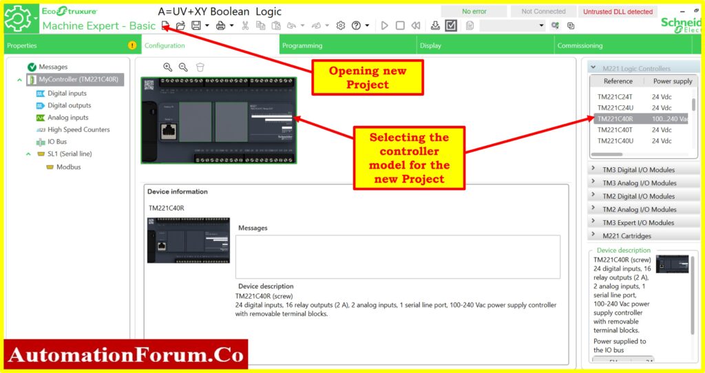
- Launch the EcoStruxure Machine Expert Basic software on your computer.
- Select the controller type with Model.
Step 3: Create a New Project:
- Start a new project or open an existing one where you want to create the ladder diagram.
Step 4: Navigate to the Ladder Diagram Editor:
- In the software, navigate to the ladder diagram editor.
Step 5: Drag and Drop Elements:
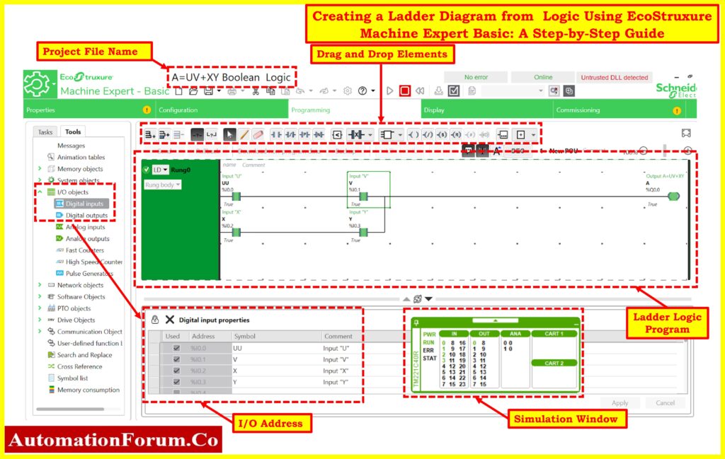
- In the ladder diagram editor, find the toolbox containing various elements such as contacts, coils, etc.
- Drag and drop these elements onto the ladder diagram workspace.
Step 6: Creating the Ladder Diagram:
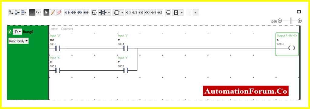
- Place input contacts for U,V,X, and Y onto the workspace.
- Create two logical AND operations:
For UV: Connect contactsU(%I0.0) and V(%I0.1) in series.
For XY: Connect contacts X(%I0.2) and Y(%I0.3) in series.
- Create a final logical OR operation by connecting the outputs of the UV and XY are OR operations in parallel.
- Connect the final output to a coil or output contact representing A(%Q0.0).
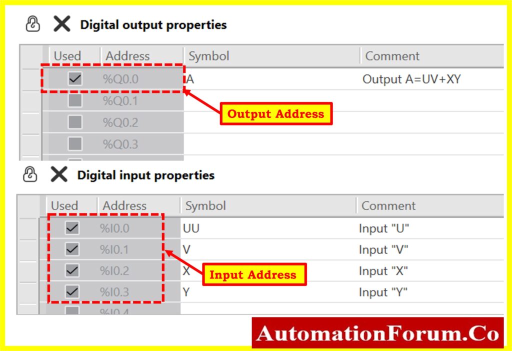
I/O Objects
The Digital inputs and outputs are listed below.
- Digital inputs: U, V, X, Y (connected to %I0.0, %I0.1, %I0.2, %I0.3 respectively)
- Digital output: A (connected to %Q0.0)
Step 7: Compile and Download Program:
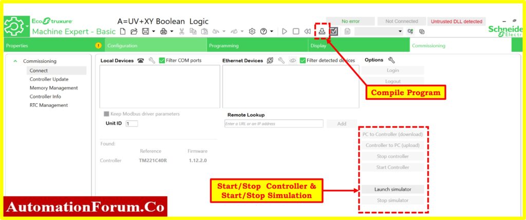
- Compile the ladder logic program within the EcoStruxure Machine Expert Basic software.
- Ensure there’s no physical PLC connected, as the simulation will be conducted entirely within the software environment.
- Download the compiled program to the software’s virtual environment.
Step 8: Activate Simulation Mode:
- Before starting the simulation, activate the simulation mode within the software.
- This mode enables the software to simulate the behavior of the PLC and execute the ladder logic program without any physical hardware.
Step 9: Start Controller (Run Mode):
- Within the simulation environment, initiate the “start controller” or “run mode” function.
- This action instructs the software to execute the ladder logic program as if it were running on a physical PLC.
Step 10: Input Test Data and Monitor Simulation Status:
A truth table shows all possible combinations of inputs along with their corresponding outputs.
For the expression A=UV+XY, where U, V, X, and Y are inputs and A(%Q0.0) is the output, the truth table would look like this:
| Input U (%I0.0) | Input V (%I0.1) | Input X (%I0.2) | Input Y (%I0.3) | Output A (%Q0.0) |
| 0 | 0 | 0 | 0 | 0 |
| 0 | 0 | 0 | 1 | 0 |
| 0 | 0 | 1 | 0 | 0 |
| 1 | 0 | 0 | 0 | 0 |
| 0 | 1 | 0 | 0 | 0 |
| 0 | 0 | 1 | 1 | 1 |
| 1 | 1 | 0 | 0 | 1 |
| 1 | 1 | 1 | 1 | 1 |
| 1 | 0 | 1 | 0 | 0 |
| 0 | 1 | 0 | 1 | 0 |
| 1 | 1 | 1 | 0 | 1 |
| 0 | 1 | 1 | 1 | 1 |
| 1 | 0 | 1 | 1 | 1 |
| 1 | 1 | 0 | 1 | 1 |
- Input various combinations of U, V, X, and Y into the simulation environment.
- Observe the behavior of the ladder logic program and verify that the output.
- For the output A(%Q0.0) to be ON, either UV or XY (or both) should be activated. This is because they are connected in parallel, and if any of them is closed (activated), the current will flow through to the output coil.
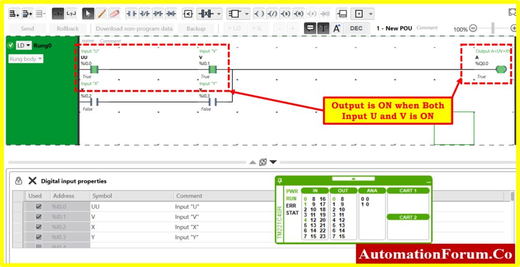
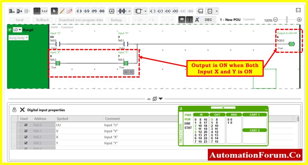
- Turning ON both U and V or both X and Y will activate the outputA.
- If only one of the pairs, eitherU and V or X and Y, is activated, the output A will still turn ON due to the OR logic gate configuration.
- Output A(%Q0.0) matches the expected results based on the truth table.
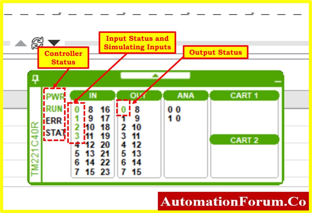
- Monitor the simulation status within the software interface to ensure that it is running without errors.
- Check simulated data, such as input and output status, program execution status, etc., to confirm proper operation.
Click here to know more about PLC Learning Articles


