Calibration
How to calibrate flow transmitter for Capillary type
Calibrate flow transmitter for Capillary type Material
Data sheet
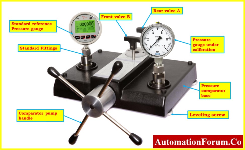
Pressure calibrator (std)
Multimeter (std)
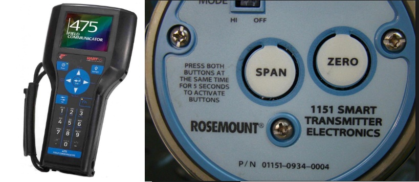
Hart communicator
Step
*Ask panel man to put the controller in manual mode for control loop and to put it on MOS for ESD loop.
*Hook up HART Communicator and verify some parameters by refer to data sheet. Typical parameters are, tag number, PV, LRV and URV.
*Isolate the instrument from the process..
*Open vent valve at drip ring and open plug at the top of the drip ring (if available) to release the process pressure
*Clean the liquid inside the drip ring and put back the plug for high side only (if available).
*Connect pressure calibrator to high side of manifold
*Expose the low side to atmosphere
*Hook up a multimeter in series with the signal to the DCS to measure current signal.
*Apply pressure as per data sheet LRV (normally 0mmH2O)
Multimeter should show 4mA
If not, do zero adjustment at transmitter using HART Communicator
Multimeter should show 20mA
If not, do span adjustment at transmitter using HART Communicator
*Verify the linearity by increasing and decreasing the pressure (0%,25%,50%,75%,100%,75%,50%,25% and 0%of range)
*After completion of the job ask panel operator to put loops back in normal mode or normalize the MOS
*Fill the calibration form and file it for future reference.
Example calculation
Instrument calibrated range: 0 – 2500 mmH2O
Process calibrated range: 0 – 130 m3/h
Q =K P
0% 0 mmH2O = ( 0/2500) x 130
= 0 m3/h
50% 1250 mmH2O = ( 1250/2500) x 130
= 91.9 m3/h
100% 2500 mmH2O = ( 2500/2500) x 130
= 130 m3/h


