
What is a control valve flashing?
- When a process fluid has flowed through restriction of the control valve. There is an increase in the velocity of the process fluid.
- Flashing can be predicted by the Continuity equation
- The continuity equation states that “For any flow rate the product of fluid density, flow area, and its velocity remains constant”.

- The kinetic energy of the fluid molecules is increased when the velocity of the flowing fluid through the constrictive passage of the control valve is increased.
- The potential energy decreases correspondingly in the form of fluid pressure.
- The fluid pressure is varied during the flow stream within the valve such that the pressure of the fluid is reduced in constriction of the control valve trim. And the flow recovers in the wider areas after the constriction of the valve body.
- When the liquid is throttled by the valve, the absolute pressure of the liquid always falls below the vapor pressure, when the liquid starts boiling.
- This phenomenon is known as flashing.
- Control valve flashing is an unexpected condition.
- By rapid expansion of liquid to vapor the flow through the valve becomes choked by the effect of liquid boiling at the maximum constriction.
- Flashing is harmful to the trim of the control valve. As fluid starts boiling the formation of minute liquid droplets at high velocity destroys the metal by corrosion passing through the plug and seat surface of the valve.
- The flashing effect in the valve sounds like sand particles flowing through the valve.
- The pressure recovery factor is an important parameter to predict a valve flashing.
- The pressure recovery factor is calculated by comparing the total pressure drop of the inlet to the outlet versus the pressure drop from the inlet to a minimum pressure.
- The pressure recovery factor is calculated mathematically by the ratio of the square root of the difference of upstream to downstream pressure to the difference of upstream to vena contracta pressure.
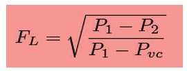
Where,
FL = Pressure recovery factor.
P1 = Upstream pressure
P2 = Downstream pressure
Pvc = Vena contracta pressure
The below conditions define various pressure recovery factors with the same pressure drop for different control valves.
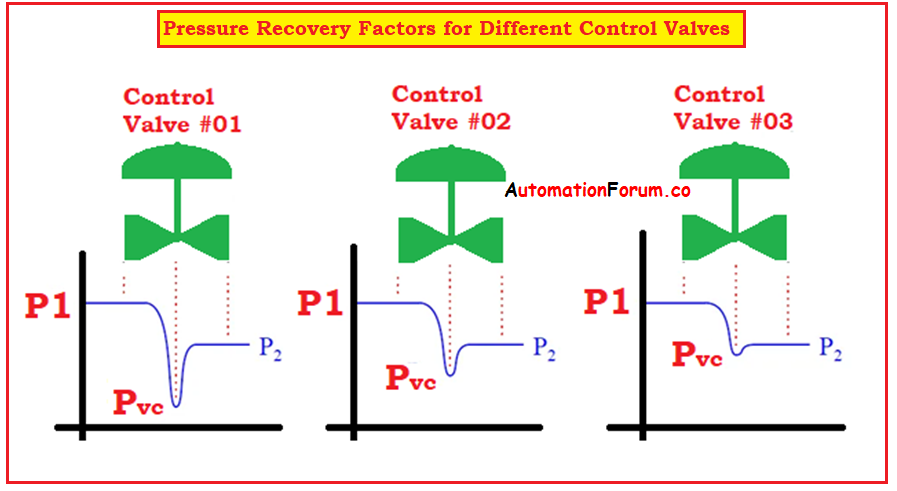
- Control valve 1 indicates fluid pressure at vena contracta to downstream be increased at the lowest pressure recovery factor. Here the vena contracta is too low so this valve is subjected to flashing in liquid service.
- Control valve 3 is best suited to avoid the valve flashing, as indicates that it has the least number of pressure recoveries with a high-pressure recovery factor near unity.
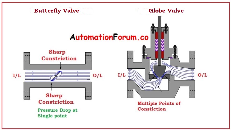
- Butterfly, Ball, and Globe valves are the most powerful pressure recovery factor. The flow path for the fluid in these valves is more complex compared to other types of valves available on market.
- In turbulent motion, the flowing fluid has a chance of dissipating its energy resulting in a higher pressure drop for minimum restriction.
Now to check which valve has the least pressure recovery factor and which is the most subjected to flashing. Now let us compare these Butterfly valves and Globe valves.

- The globe is the best suited for distributing pressure losses equally through the overall flow. But the pressure drop at the butterfly valve is only at the constriction between disk and valve body which is a straight path that offers minimum restriction.
- For any pressure loss, the butterfly valve experiences a higher pressure recovery and a lower pressure recovery factor than the globe valve.
- The butterfly valve is more subjected to flashing than the globe valve.
What are the problems that cause flashing in a control valve?
Two main problems cause flashing are
- Erosion
- During flashing the outlet flow is liquid and vapor.
- The vapor droplets carry liquid when the flashing is increased.
- The flowing fluid behaves as a solid particle as it strikes the internal part of the valve body.
- Fluid velocity at the valve outlet can be minimized by increasing valve opening which may reduce the effect of damage to the valve body.
- Angle valves are good for flashing that occurs downstream of the valve.
- A common fact known to us is the wet steam flow through the valve containing water or liquid droplets forced at high velocity is the cause of valve erosion.
- Reduced Capacity
- In case of flashing the required space is increased as the flowing fluid is converted to a vapor state.
- The capacity for the valve to control maximum flow is limited due to reduced area.
- When the flow capacity is limited the term choked flow is applied.
Choked flow: it is a position when the flow rate through the valve remains constant or fixed with the reduction in downstream pressure.
- Cavitation and flashing are common phenomena that can occur under certain flow conditions when a control valve is used for liquid application
- For higher fluid velocity through the valve, the pressure drop in the fluid occurs when the fluid starts to bubble or flash
- To illustrate the concept of flashing the control valve can be modified as an orifice plate in case of cavitation and then use the changes in pressure and velocity.
- The change in fluid pressure and fluid velocity during flashing is shown below diagram.
- When the control valve downstream pressure drops below the vapor, some part of the liquid at the downstream side is vaporized and remains in the vapor state.
- Fluid flow on the downstream side of the control valve is part liquid and vapor.
- The subsequent flow of the fluid through the valve is choked.
- The flow rate is not increased when the downstream pressure decreases.
- Flashing causes some mechanical problems such as erosion and vibration.
- Due to the larger vapor volume compared with liquid the velocity is high.
- More resistant materials must be used because higher fluid velocity is erosive and there is a possibility of flashing in the valve.
How to minimize flashing damage in the control valve?
Flashing damage in control valves is minimized
- Hard face trim materials such as stellite or tungsten must be used.
- Using corrosion-resistant body materials.
- Reducing the flow velocity by increasing the valve opening.
- Use of angle valve or flow over the plug.
What is the effect of flashing and cavitation?
Both flashing and cavitation leads to harmful effects on control valves and on the process if the valves are not maintained properly.
What is the difference between flashing and cavitation in a control valve?
Flashing
- Flow rate is reduced and pressure is decreased.
- The liquid must accelerate to maintain continuity as the liquid comes across reduced areas to hold on toa constant volumetric flow rate.
- Flashing also causes harmful damage to the valve surface in the form of erosion in the valve plug.
Cavitation
- Causes wear and tear on the valve.
- Noise and vibration damages the surrounding equipment
- The valve surface gets damaged when the vapor bubbles collapse.
- It causes high-pressure shock waves in the system.
- It causes micro-jets to hit the valve surface at a higher velocity and results in pitting.
How can we predict the occurrence of flashing and cavitation in a valve?
- Every industrial process must be designed and constructed in such a way as to minimize or eliminate the effect offlashing and cavitation in predictable regions.
- But these situations occur unexpectedly,
- Hopefully, we find the signs of loud mouth signs of erosion and pitting.
- The only way to determine the effect of flashing and cavitation is that we must listen to the sound.
- The Flashing sounds like hissing, and cavitation sounds like a popping sound.
- Note that both of these sounds can be quite loud, compared to a fogger machine.
How do I prevent flashing and cavitation?
Protecting the valve and process equipment is the most important task to prevent damage from flashing and cavitation.
There are 3 system level controls and 2 control valve level controls
System level controls
- Install the control valve in a high-pressure area to increase the fluid pressure and the vapor pressure.
- Use of an orifice plate or a second valve downstream to restrict the flow and to increase the backpressure. This increases the fluid pressure and reduces the fluid velocity.
- Establish a non condensable gas line into the flow stream to prevent the collapsing of bubbles that cause pitting and erosion.
Control valve level controls
- Select the valve materials that minimize the cavitation damage.
- Using anti-cavitation trim design. These trim designs handle cavitation in various ways, such as pressure drop staging, dividing the flow into multiple paths, and redirecting the flow away from the surface.


